
SCHOLARSHIP APPLICATION: (Deadline: APRIL 30th, 2027)
Please ensure all fields are filled in completely.To view previous winner: Click Here
(IF YOU HAVE ANY QUESTIONS, PLEASE EMAIL THE PROGRAM ADMINISTRATOR AT RYAN@STUDENTSCHOLARSHIPS.ORG)
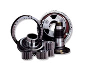
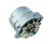
Starters for Forklifts

Forklift Starters - Today's starter motor is usually a permanent-magnet composition or a series-parallel wound direct current electrical motor together with a starter solenoid installed on it. When current from the starting battery is applied to the solenoid, mainly through a key-operated switch, the solenoid engages a lever which pushes out the drive pinion which is situated on the driveshaft and meshes the pinion with the starter ring gear that is found on the engine flywheel.
The solenoid closes the high-current contacts for the starter motor, which starts to turn. When the engine starts, the key operated switch is opened and a spring within the solenoid assembly pulls the pinion gear away from the ring gear. This particular action causes the starter motor to stop. The starter's pinion is clutched to its driveshaft by means of an overrunning clutch. This allows the pinion to transmit drive in only a single direction. Drive is transmitted in this manner through the pinion to the flywheel ring gear. The pinion remains engaged, for example in view of the fact that the operator fails to release the key as soon as the engine starts or if the solenoid remains engaged in view of the fact that there is a short. This actually causes the pinion to spin separately of its driveshaft.
This aforementioned action stops the engine from driving the starter. This is actually an important step as this particular type of back drive would allow the starter to spin really fast that it can fly apart. Unless modifications were made, the sprag clutch arrangement would stop utilizing the starter as a generator if it was employed in the hybrid scheme mentioned earlier. Usually an average starter motor is meant for intermittent utilization which would prevent it being utilized as a generator.
Hence, the electrical components are meant to be able to operate for just about under thirty seconds to be able to avoid overheating. The overheating results from very slow dissipation of heat because of ohmic losses. The electrical components are designed to save cost and weight. This is the reason nearly all owner's manuals used for vehicles recommend the driver to pause for a minimum of 10 seconds after each and every 10 or 15 seconds of cranking the engine, if trying to start an engine which does not turn over right away.
The overrunning-clutch pinion was introduced onto the marked during the early part of the 1960's. Before the 1960's, a Bendix drive was used. This drive system operates on a helically cut driveshaft which has a starter drive pinion placed on it. When the starter motor begins spinning, the inertia of the drive pinion assembly enables it to ride forward on the helix, hence engaging with the ring gear. When the engine starts, the backdrive caused from the ring gear allows the pinion to exceed the rotating speed of the starter. At this point, the drive pinion is forced back down the helical shaft and thus out of mesh with the ring gear.
During the 1930s, an intermediate development between the Bendix drive was made. The overrunning-clutch design which was made and introduced in the 1960s was the Bendix Folo-Thru drive. The Folo-Thru drive consists of a latching mechanism along with a set of flyweights in the body of the drive unit. This was better because the typical Bendix drive used so as to disengage from the ring as soon as the engine fired, even if it did not stay running.
When the starter motor is engaged and begins turning, the drive unit is forced forward on the helical shaft by inertia. It then becomes latched into the engaged position. As soon as the drive unit is spun at a speed higher than what is achieved by the starter motor itself, like for example it is backdriven by the running engine, and then the flyweights pull outward in a radial manner. This releases the latch and permits the overdriven drive unit to become spun out of engagement, therefore unwanted starter disengagement could be prevented prior to a successful engine start.
Click to Download the PDF
Forklift Parts

TOLL FREE: 1-888-695-7994
Medicine Hat, Alberta
forkliftpartsmedicinehat.ca
Email Us
About Us